Aescape Robotic Massage
System
Role
Industry
Sr Mechanical
Design Engineer
Robotics & AI
Wellness Tech
SolidWorks
Python, MATLAB
Jira, Smartsheet,
Notion, Slack
Tools
Duration
2+ years
Mechanical Design
Product Management
Manufacturing & Supply Chain
Skills
Design & Development of Advanced Robotic Systems
At Aescape, I contributed to the design and development of a cutting-edge robotic system aimed at revolutionizing physical therapy.
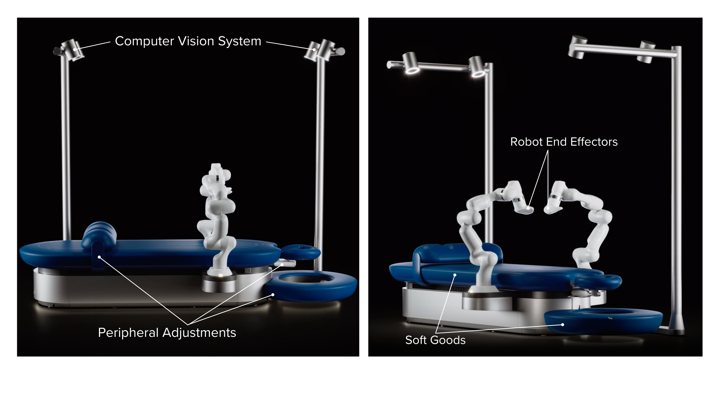
As the second mechanical engineer on the team, I played a key role in the end-to-end product lifecycle of four subsystems including the computer vision system, actuated adjustment platform, robot end effectors and soft goods. I designed and managed these systems from conceptual design through mass production.
Design Process
Computer Vision System Case Study

1. RESEARCH |
I identified stability issues with the existing ToF sensor platform prototype, which the computer vision team had identified as a major concern. The system was highly sensitive to vibrations and impacts, compromising sensor data integrity during movement and operation.
I conducted preliminary research by:
Collaborating with computer vision engineers to assess current design limitations
Evaluating stability and vibration modes of initial V1 prototype design through measurement
Working with computer vision engineers to understand the impact of vibration on ToF sensor data during operation
Researching the architecture of similar systems & structures (i.e. light poles, traffic signals, etc.) to understand how structures with a similar moment of inertia achieve stability in extreme conditions
2. DEFINE |
Smartsheet
Collaborated with key stakeholders to define system requirements:
Met with computer vision engineers to determine vibration amplitude limits and ToF sensor position (x,y,z) for optimal point cloud resolution and field of view.
Collaborated with Industrial designers and UX researchers to determine optimal color, material and finish for accessibility, sleekness and visual appeal
Met with product researchers and the sales team to evaluate the unit's volumetric constraints based on its installation environment. Reviewed building codes to ensure compliance with IBC requirements for residential and commercial spaces.
Met with electrical engineers to discuss electrical hardware and cabling requirements for functionality and reliability.
3. DESIGN |
SolidWorks, CAD , FEA, MATLAB
Once all requirements were defined, I modeled a basic design of the system in CAD and used FEA software to determine optimal material, stock thickness and construction that would satisfy performance, functional, design and regulatory requirements.
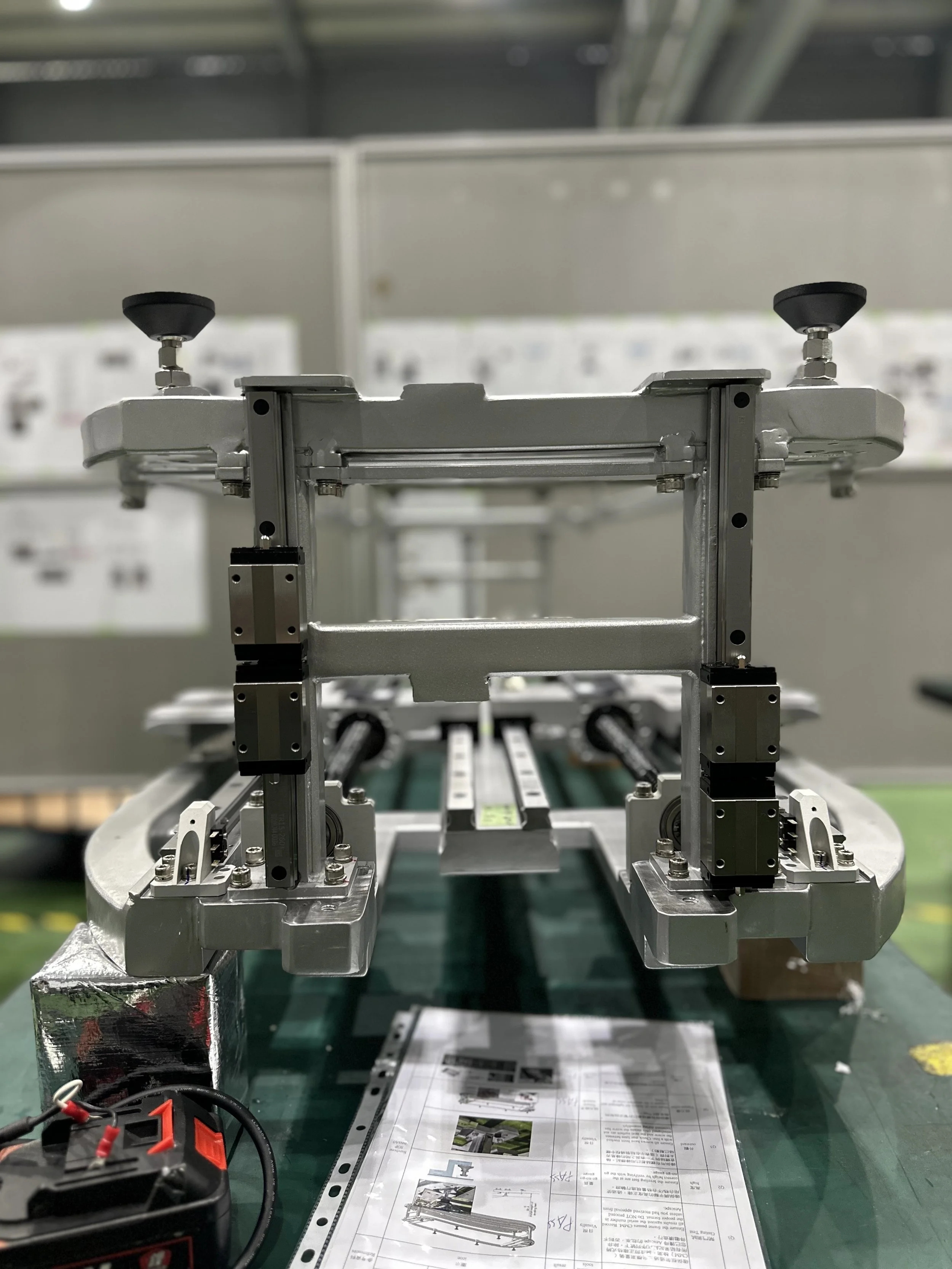
4. PROTOTYPE |
3D Printing
Throughout the design process, I 3D printed small sections of the system to validate interlocking features and hardware fit.
Once the design concept was finalized, I worked with local machine shops and vendors to produce a preliminary functional prototype of the system.
4. TEST & ANALYZE |
Python
Once I had procured the functional prototype I evaluated the system’s performance based on functional, performance, manufacturability and installation criteria:
I conducted a mechanical vibration analysis of the system using laser displacement sensors to measure vibrational amplitude, frequency, and damping rate.
I collaborated with computer vision engineers to assess sensor performance and sensitivity.
I met with manufacturers on-site in Taiwan to evaluate manufacturability, optimizing the design for high precision, cost efficiency and volume production.
I worked with industrial designers to assess the unit’s accessibility and refine its dimensions for an optimal look and feel.
I coordinated with electrical engineers to ensure cable routing was optimized for signal integrity and power distribution.
I supervised and supported field installation engineers to assess the unit’s assembly process during in-field install.
5. REFINE & ITERATE |
Utilizing the feedback from initial testing, I iterated the design to achieve optimal performance before the launch deadline:
50% reduction in system vibration amplitude and a 30% reduction in recovery time compared with the V1 prototype of the system, reaching the ideal metrics for vibration amplitude and damping rate.
Minimized the requirement for recalibration by 70%, saving the computer vision engineers 40 minutes of recalibration time for each session.
Minimized manufacturing costs while optimizing for system precision, quality and finish, achieving a 20% reduction in cost from the V1 system design (~$4000 per system)
Optimized the design using feedback from the assembly team to reduce assembly time by 30%, saving the company $300+ per install
PROJECT HIGHLIGHTS